September 15, 2015
Andrew:
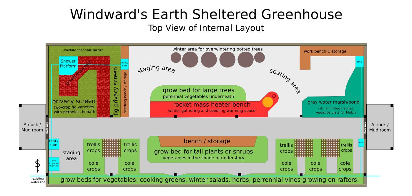
Top view of the greenhouse detailing a preliminary layout of the interior space including the placement of growbeds, path and water access, staging areas, working space, back-up mass-heater and more.
Click on the image to enlarge.
Many years ago, long before my time at Windward, the community had an understanding that a large, earth sheltered greenhouse could be an important part of the food system of the community.
Over several years, land was excavated and a northern 6 foot earth sheltered concrete wall was built - one wheelbarrow load of concrete at a time.
The greenhouse has been on our mind for many years, however the capital (money, time, strategic focus, and skilled-enough labor) of the community had not converged to enable us to move forward on it.
This past year, we met a Seattlite and community supporter name Walker through Windward's work in establishing Herland Forest's
Initial designs for the greenhouse
Structural Design
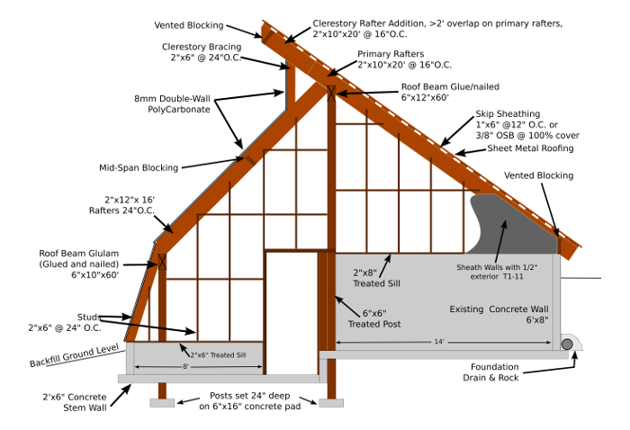
A side view of the greenhosue detailing the structural components of the posts, glulam beams, rafters, concrete footings, and stick frame walls.
The Structural system of the greenhouse is modified pole-barn with glue-laminated roof support beams and rafters.

View of the northern concrete wall that will be back-filled with earth on the uphill side.
The north, south, east and west end of the building are built on a concrete foundation wall, allowing it to be earth sheltered for an effect of a thermal mass or a "thermal battery" to regulate extreme outdoor temperatures by making use of the near constant temperature of the earth at 55 degrees Fahrenheit at about 3 ft underground.
The design of the greenhouse is very similar to the way Windward's dining hall was constructed.
Earth sheltering has proven to be a phenomenal success in our climate - dramatically lowering the cost of heating and cooling in the extreme months by virtue of the thermal battery created by the mass of the earth built up behind the building.
The greenhouse will be earth sheltered on all sides, creating in effect a kind of underground building.

Top View of the greenhouse detailing the layout of concrete walls, and internal posts.
Two sets of 6x6in posts places 12ft O.C. hold up two seperate glulams at the points where the three different roof pitches converge.
Rafters on the north and south end of the building run from the glulam down to the concrete foundation walls which will be mostly buried with earth. Rafters in the central roof run between the two glulams.Passive Solar Design Elements
As with most energy-efficient 4-season greenhouses, Windward's earth-sheltered greenhouse is designed with roof pitches optimized for the times of year when we need the most solar gain for plant growth.
The southern most roof (really more of a slanted buttress wall) pitch is 110 degrees from the horizon, almost perpendicular to the winter sun angle of -21.5 degrees from the horizon.
The height of the building, combined with the amount of southern facing roof, allow the winter sun angle to penetrate deep into the greenhouse and fall upon the northern interior wall. This allows for a maximum amount of radiate heat gain throughout the coldest months.
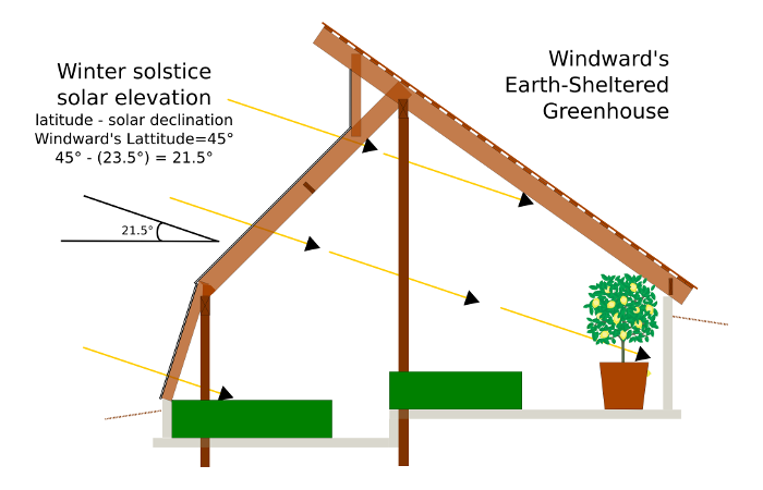
Winter Sun Angles
The main southern roof span is at 45 degree from horizon, perpendicular to the equinox sun angles.
This will allow us optimal light in the "quickening" time of year, when we will be starting most of our summer annual garden plants for planting out in other outdoor garden spaces.

Equinox Sun Angles
The cantilevered clerestory of the northern roof blocks a significant amount of the summer sun, helping to minimize unwanted solar gain in the hot summer months while still allowing direct sun to reach the front growing beds.

Summer Sun Angles
Design of the Interior
Below is an initial layout of the interior of the greenhouse.
It shows several diverse features including:
- Growing beds (green) for different sized plants
- generous central through paths and staging areas
- working space for starting and staging seedlings
- Water pipes, sinks and other irrigation infrastructure
- An interior shower space for community use which doubles as a watering system for deep rooted productive trees (like figs) which also provide a living privacy screen for the shower
- Rocket-mass-heater bench for emergency winter heating and seedling warming bench
- Benches for community gathering that double as storage space
- A space along the rear wall for large potted plants and water tank heat sinks.
- The mudrooms on either end of the greenhouse for covered storage space that also serves as an airlock for the greenhouse.
Top view of the greenhouse detailing a preliminary layout of the interior space including the placement of growbeds, path and water access, staging areas, working space, back-up mass-heater and more.
Click on the image to enlarge.
To look at some numbers, this layout allows for just under 600 square feet of growing beds, as well as small pond for grey water reclamation and a large swath of the back wall for overwintering large potted plants.
View of the Exterior
Below is a front view of the exterior of the greenhouse. It is presented here primarily to show the multi-layered planting of vegetables, vines, herbs, shrubs, and trees planned for the interior of the greenhouse.
The use of vertical layers within the greenhouse allow for greater productivity overall, as well as a climate moderating effect of shade within the greenhouse for the intense summer sun.
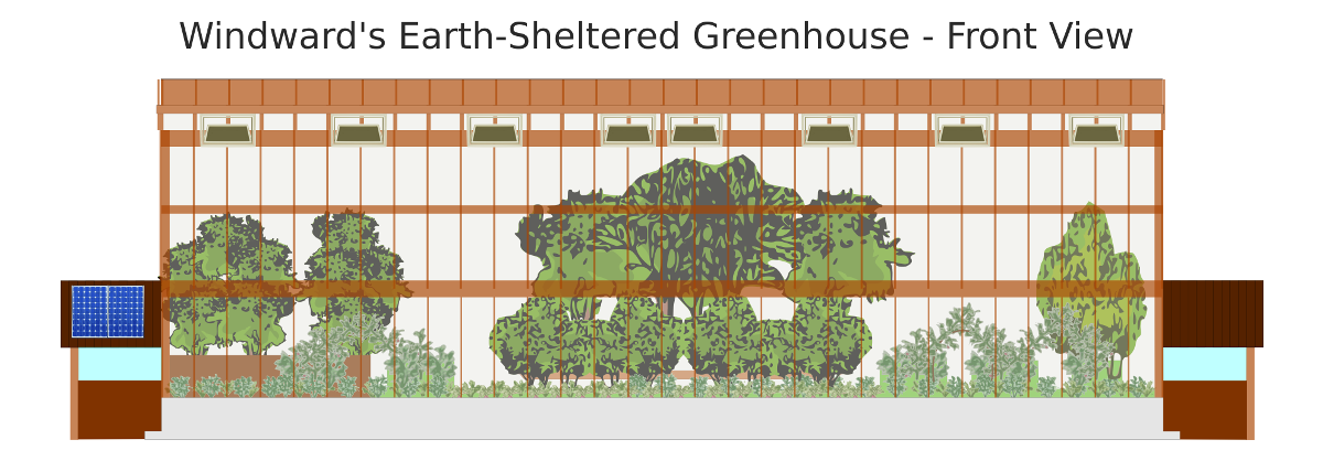
Front view of the greenhouse exterior including the how the vegetation inside the building will likely look when more mature. This image does not include any of the landscaping that will be put in around the greenhouse.
Click on the image to enlarge.
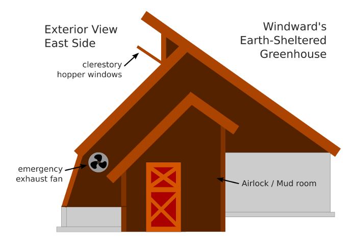
Below is a side view of the exterior of the building. You can see the roof pitches, concrete foundations, mud room, clerestory windows and emergency side wall ventilation fans.
Pouring the Southern Concrete Foundation
This spring we got underway excavating and setting up the form for the southern concrete foundation
The first job was to get the length of the building to approximately the right depth and level from end to end. We did this with a small bulldozer affectionately named Wall-E.

Beginning to layout the footing form work for the southern stem wall.
Next we did the finishing work of levelling the pad for the footing with good old shovels, string lines and a water level.

A view of the completed footing forms, ready for the plywood foundation forms to go up.
The construction of the footings for the southern wall as pretty straightforward. two runners of 2"x6" boards were laid level and spaced ~21 inches apart in order to take the metal spacer bars which also receive the brackets which the vertical plywood sheets attach to.
The runner boards were supported by concrete stakes and backfilled on the outside to help the boards stay in place under the load of the pouring of concrete.


Closeup of the footing forms before and after the plywood has been installed.
Two sets of 1/2 rebar were laid in between the runners, and the metal brackets for the vertical plywood forms were secured to the center line of the metal spacers with self-taping metal screws.
These brackets will be subsumed by the concrete of the wall. The slots that the plywood sit in will be outside the wall in order that we can easily remove the plywood forms for reuse in other concrete pour projects.

A view down the completed forms as we were beginning the concrete pour. The downhill side of the forms were braced to ensure they stayed straight as the they were filled.

We began by pouring the footings. Here you can see our neighbour helping out with his concrete pumper. Opalyn (steward member of Windward) and Yosef (Apprentice) ready with the vibrator to settle bubbles in the concrete.

Opalyn and Yosef making the rounds with the vibrator.

Andrew Bishop (Apprentice) helping to scrap the excess off of the footings. This aids in removing the forms later.

Myself scraping the top of the wall smooth between the anchor bolts.
The whole process of pouring the wall took only 15-20 minutes in total. Quick work in comparison to the excavation and set up of the forms!.